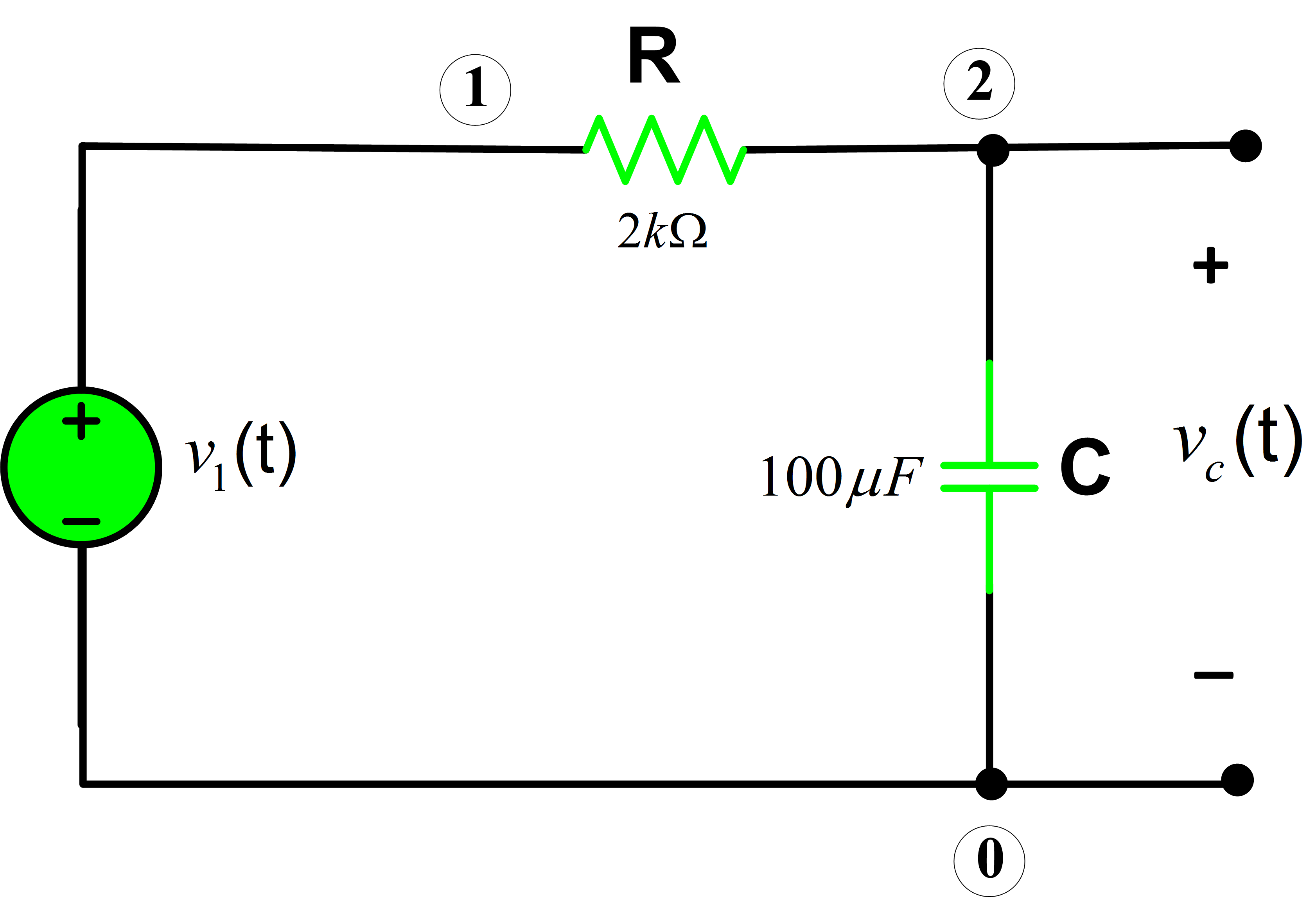
Rc Circuit E Ample Problems
Rc Circuit E Ample Problems - When charged, the potential difference across the terminals of the capacitor is 9v 9 v. A simple rc circuit as shown in figure 20.8.1 20.8. Web the solution for this differential equation is. Web in an rc circuit connected to a dc voltage source, voltage on the capacitor is initially zero and rises rapidly at first since the initial current is a maximum: Where v 0 is the voltage at time t = 0. The battery's emf is \mathcal e=12\, {\rm v} e = 12v, c=8\, {\rm \mu f} c = 8μf, r=500\, {\rm k\omega} r = 500kω. The instant power is applied, the two capacitors appear as short circuits. Discussion 2 µf 100 kω. This is called the natural response. Rc circuits click here to see the solutions.
Determine the initial and steady state currents. Vc is the voltage across the capacitor; Web the rc circuit has thousands of uses and is a very important circuit to study. Vs is the supply voltage; The problems target your ability to apply concepts of potential, capacitance, resistance, and current in order to analyze transient rc circuits. As presented in capacitance, the capacitor is an electrical component that stores electric charge, storing energy in an electric field. A basic rc circuit, initial state.
Web the rc circuit has thousands of uses and is a very important circuit to study. We solve for the total response as the sum of the forced and natural response. Not only can it be used to time circuits, it can also be used to filter out unwanted frequencies in a circuit and used in power supplies, like the one for your computer, to help turn ac voltage to dc voltage. After a period equivalent to 4 time constants, ( 4t ) the capacitor in this rc charging circuit is said to be virtually. A simple rc circuit as shown in figure 20.8.1 20.8.
Again, rc \rightarrow rc → is called the time constant of the circuit, and is generally denoted by the greek letter \tau. A capacitor of capacitance 1000 μf is connected to a resistor of resistance 150 kω and a battery of 1.5 v in series. T is the elapsed time since the application of the supply voltage; Not only can it be used to time circuits, it can also be used to filter out unwanted frequencies in a circuit and used in power supplies, like the one for your computer, to help turn ac voltage to dc voltage. How long wiil the circuit take to reach steady state (approximately). The instant power is applied, the two capacitors appear as short circuits.
Web the solution for this differential equation is. We solve for the total response as the sum of the forced and natural response. Web what we're building to. What factors contribute to the capacitance of a capacitor? By james bourassa john rosz.
1) rc circuit review 2) equations for rc 3) time response of rc circuits 4) rc filters. In this section we see how to solve the differential equation arising from a circuit consisting of a resistor and a capacitor. The time constant for an rc circuit is τ = r ⋅ c. We solve for the total response as the sum of the forced and natural response.
Vs Is The Supply Voltage;
Given this equivalent, we can see that shorting c2 c 2. For the rc circuit in the figure, r1 = 12:0kω and r3 = 3:00kω. What factors contribute to the capacitance of a capacitor? An uncharged capacitor and a resistor are connected in series shown in the figure below.
Web An Rc Circuit Is A Circuit Containing Resistance And Capacitance.
(easy) a 200ω resistor, a 5000μf capacitor, a switch, and a 10 v battery are in series in a single circuit loop. Determine the initial and steady state currents. (b) the maximum charge on the capacitor. 922k views 6 years ago electronic circuits.
A 50 V Ac Is Applied Across An Rc Series Network.
Web figure 8.3.1 : Consider the circuit shown in figure 8.4.1. Web the solution for this differential equation is. Where v 0 is the voltage at time t = 0.
We Solve For The Total Response As The Sum Of The Forced And Natural Response.
Rc circuits click here to see the solutions. Becomes smaller, the capacitance goes up. T is the elapsed time since the application of the supply voltage; How does an rc circuit respond to a voltage step?


